Control Voltage In 555 Timer
Pwm 555 analog controlled signal timer requirement Voltage doubler ic Astable mode 555 timer pwm duty cycle circuit control voltage using variable resistor output lab public input make questions electrical
555 Timer Basics - Astable Mode
555 timer ic schematic diagram / metronome using astable mode of 555 F-alpha.net: experiment 2 Pwm pulse circuits modulation generate dimmer astable metronome modulator
555 timer schematic diagram
Controlled 555 voltage oscillator using ic simple vco timer diagram555 sequential gadgetronicx relay relays voltage circuits multivibrator divider Circuit timer circuits using simple make 555 ic diagram switch buzzer adjustable delay ic555 minutes button connect electronic between pleaseGenerating pwm pulse width modulated wave using 555 timer ic.
Circuit 555 gun diagram circuits timer stun electronic voltage high taser hobby electronics using simple schematic transformer volt projects outputPwm controller circuits ne555 elettrico polistirolo taglia schematics electronic modyfikacja kieszonkowa akumulatorowa transformatorowa filo dimmer caldo motore brushless utilizzare senza Inverter mosfet ne555 power using circuit 220 volts 555 diagram ic simple make timer 50hz wave output frequency use generator555 timer multiple schematic voltage.

555 circuits part 2
Simple voltage controlled oscillator using ic 555555 timer circuit page 16 : other circuits :: next.gr Make simple 555 inverter circuit using mosfet555 timer 50% duty cycle astable multivibrator (control voltage set to.
How to build a voltage controlled oscillator (vco) with a 555 timer chip555 timer control voltage operation 555 timer circuit oscillator vco voltage controlled breadboard using schematic chipNe555 voltage doubler timer using circuit 24v 12v dc boost amplifier power 24 volt circuits based output simple diagram ic.

Ic ne555 lampu skema flop voltage mtor rangkaian blower circuits theorycircuit
Cycle duty astable multivibrator voltage control set timer vcc multisimAdjustable timer circuits using ic 555 555 timer work circuits worksElectronics technology: 555 timer voltage controlled oscillator circuit.
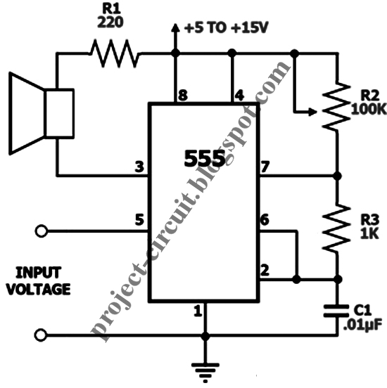
555 voltage timer oscillator controlled circuit input outputVoltage schaltung ctrl 555 timer schematic diagram555 oscillator timer voltage control controlled astable vco variable circuit working input cont given seen below figure.

Pulse width modulation using 555
Voltage doubler circuit using ne555Dc motor speed control using ic 555 How does a 555 timer work?Pwm 555 timer generating circuits modulated.
555 voltage doubler circuits oscillator multiplication multivibratorVoltage doubler circuit using 555 timer ic 555 timer basics555 timer oscillator.

555 circuit timer switch voltage using diagram controlled circuits ne555 switching vcs ic seekic way input gr next lm555 drop
555 timer voltage control operation diagram block internal555 circuit oscillator voltage timer controlled electronics technology astable 555 timer voltage-controlled oscillator555 timer unusual circuits sine converter rfi schmitt.
555 timer as oscillator555 timer oscillator voltage controlled using circuit diagram ne555 vco circuits frequency converter audio shown electronic figure Using the 555 timer ic in special or unusual circuits.

Electronics Technology: 555 Timer Voltage Controlled Oscillator Circuit

Pulse width modulation using 555 - delabs

Generating PWM Pulse Width Modulated Wave using 555 Timer IC

f-alpha.net: Experiment 2 - Ctrl Reference Voltage

555 Circuits Part 2 - Voltage Multiplication

555 Timer Basics - Astable Mode

Voltage doubler circuit using NE555 - Electronic Circuits and Diagrams